66-67 Dodge Charger Source Guide
Gauges Voltage Limiter
| Posted by: Bryan (A383Wing) on 05/22/07
Most Mopars have an external style voltage limiter that plugs
into the rear of the instrument clusters. Someone at Chrysler in their
infinite wisdom decided that they would incorporate the limiter inside
the dash fuel gauge on the first generation Chargers. If the factory
limiter for some reason fails, you will get a full dose of battery
voltage through the fuel, water, & oil pressure gauges thus letting
the "smoke" out of them rendering them useless. How the originals fail
is the "points" inside the fuel gauge for the limiter stick closed for
a time and send full battery voltage through the 34 gauge silk wrapped
ni-chrome special wire that is wrapped around the bi-metal strip in
there. All it takes is a few seconds and "POOF" - gauges fried. 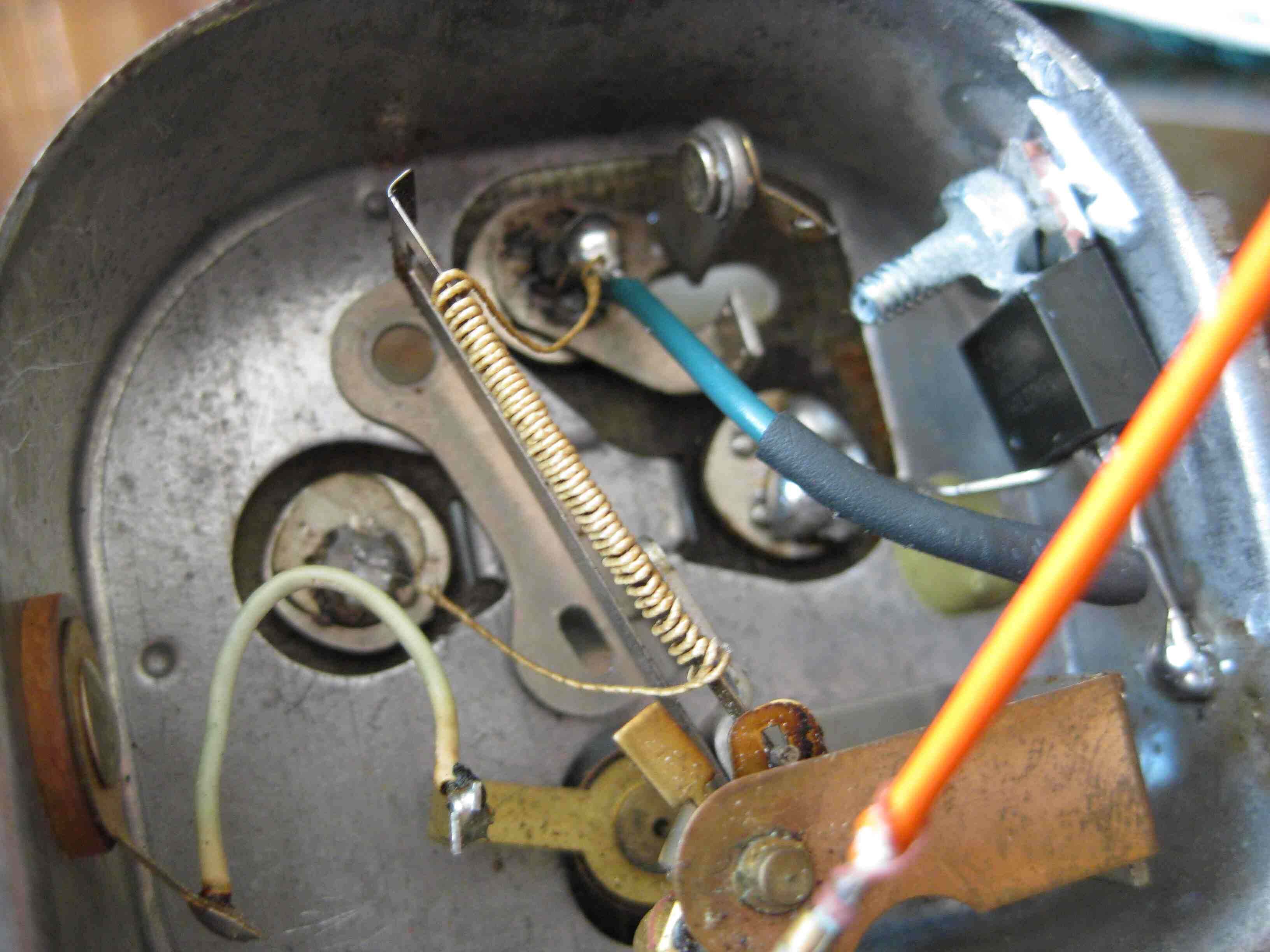
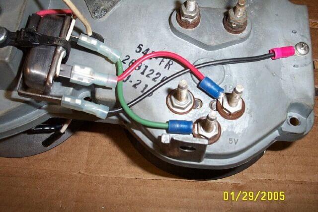
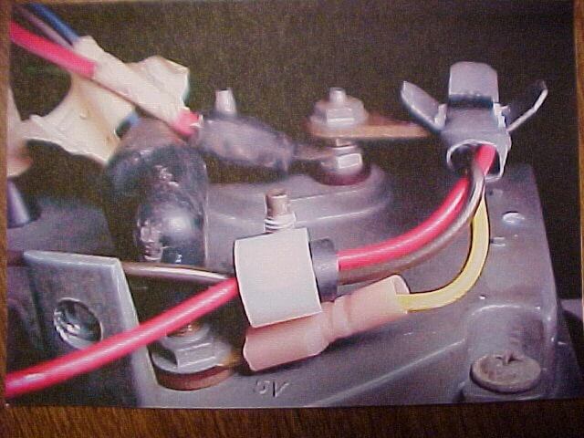
The limiter acts like the turn signal flasher does, it makes & breaks contact inside thus only allowing about 5 volts through the little fragile wires inside the gauges. What I have done is this....I get one of the "plug-in" style limiters, take it apart and remove the "points" strip....put it back together, and install a 5volt transistor along with a capacitor and mount it to the "plug-in" style limiter. The transistors I use are good all the way up to around 20volts I believe. What you would need to to to install one of these is first you have to do a little surgery on your fuel gauge and remove the limiter portion of the gauge, put the gauge back together, and mount the limiter I build to the rear of the dash and wire it into the fuel gauge pegs. 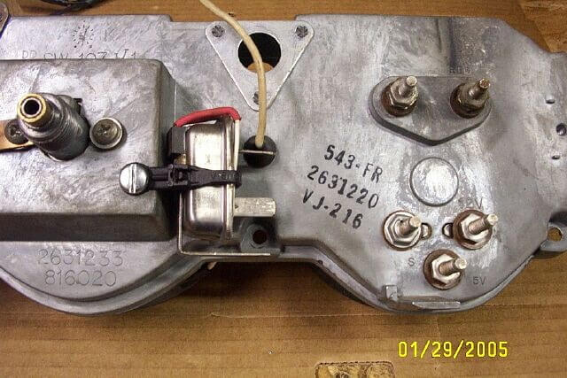
|
| Bryan will set you up with his improved voltage limiter for $40 total...$35 + $5 for packaging & shipping |
| Posted by: Ron Delvaux on 04/12/06
I picked up a limiter from NAPA for $25.00 bucks It drops 12v to 5v to the fuel, oil & temp guages. We have an antique one that is of 1967 era technology... when the old one goes it sends 12v to the guages and fries them! this replaces the old one...takes some work...remove the cluster etc... |
| Posted by Andy
Markiewicz
on 06/12/03
If it seems too much hassle for DIY, I could build and ship you one within the U.S. for $24 total. Just don't forget that the heat sink is "live",it will short if grounded. If it does, it will just heat up the reg and eventually burn it up. I tested this for a few minutes and it did not burn up, but worked fine afterward. Did not want to be leading anyone on a path toward fire hazard! Make sure everything is insulated well and away from the wiper linkage after instillation. |
| Posted by: JohnMac on 09/02/02
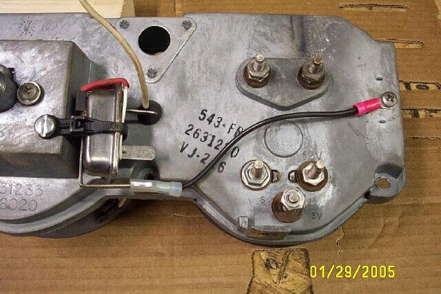
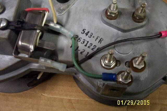
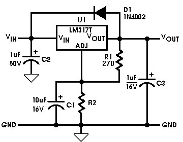
When the instrumentation for our 60s-70s MoPars was designed, electromechanical devices were still far less expensive than semiconductor devices. That is why mechanical voltage regulators were used. Today, we can buy a semiconductor device for pennies (I remember paying DOLLARS for what is now a crude transistor). It makes no sense to stay with a mechanical regulator for your dash gauges, especially when you've updated to the MoPar Performance electronic alternator voltage regulator. To my knowledge, no one (yet) manufactures a retrofit regulator for the instrument clusters. But, with modern integrated circuits, it's relatively easy to fabricate one for yourself! Before getting into the modern era, it might help to understand how the old type worked. There were two physical versions used on MoPars (they work identically). The A-body version was part of the fuel gauge; the others used a separate unit that plugged into the instrument cluster's printed circuit board. The nominal 12 volts of the car's charging system is regulated down to (approximately) 5 volts by a thermal "bimetallic" regulator, similar to that used in a home heating system thermostat except that, in this case, the bimetallic strip is heated by a nichrome (nickel-chromium) wire element. As the heater element heats up, the bimetallic strip bends. When it bends enough, it opens a set of contacts - interrupting the output (and heater) current. The bimetallic strip then cools and closes the contacts, beginning a new cycle. The up-and-down voltage variations are smoothed by a capacitor (condenser) connected to the output. Over time, the contacts wear, and the heating element can go open. This is when your temperature, fuel, and oil pressure gauges stop working. Even when they are working, they tend to fluctuate up-and-down. It was a crude system but, at the time, it was the best thing available. The New RegulatorIn the modern age, integrated circuit chips do a much better job of regulating voltage and they're very easy to use. MoPar Action Magazine presented their version of this conversion in the August 2000 issue, using the LM7805 (5 volt fixed-output) 3-terminal regulator IC. While it'll bring back your instrument cluster back from the dead, you may want something with a bit more flexibility. Because the senders and gauges vary somewhat, it'd be nice to be able to set the output of the regulator to compensate for these tolerances. That's covered by another 3-terminal regulator - the LM317.The new circuit...
Bill Of MaterialsC1 10µF, 16V Tantalum CapacitorC2 1µF, 50V Tantalum Capacitor C3 1µF, 16V Tantalum Capacitor D1 1N4002 Diode (or any 1A diode) R1 270 ohm, 5%, ¼ watt resistor R2 5%, ¼ watt resistor (see chart, above) U1 LM317T Regulator IC Misc TO-220 heatsink (or small piece of aluminum) 1000 ohm trimmer potentiometer (optional) perforated circuit board material
Building the circuit...The physical layout is not very critical at all - and it can be built on a small piece of perforated circuit board, or point-to-point. To realize the 1.5A capability of the IC, you must use a heat-sink of some kind. This can be either a store-bought type or just a small piece of sheet aluminum. C1, C2, and C3 should be "tantalum" types (don't use aluminum electrolytic types). If you can't find the exact values, somewhat higher values are OK - it's not too critical. Don't use lower voltage types, especially for C2. The resistors can be ¼ watt, ±5 or 10% tolerance types. D1 is specified as a 1N4002 (1A, 100V) rectifier diode but can be any 100V (or greater) diode rated at 1 ampere.The National Semiconductor data book specifies 240 ohms for R1 but that is not as easy to come by as a 270 ohm resistor so, the chart (above) shows the calculated output voltage based on the latter. If you'd like to be able to have a variable rather than a "selected" voltage adjustment, you can use (say) a 510 ohm resistor in series with a 1000 ohm potentiometer in place of R2. That will give you an adjustment range of 3.61 to about 8.2 volts. It's only a few pennies more. IMPORTANT NOTES:Before installing the new circuit, remove the old regulator.Since the mounting tab for the U1 is also the output terminal, the heatsink MUST be electrically isolated from everything else! Observe the polarity of C1, C2, and C3. Some vendors mark the positive terminal; others mark the negative terminal. When making connections, use a low-wattage soldering pencil; DO NOT use solder that has an acid-core flux!
How it works:The '317 is an adjustable regulator with 1.5A of current capability - more than enough to handle the ½ ampere of current demand by the gauges. R1 sets the current supplied to the adjustment terminal of U1. R2 sets the output voltage. C2 functions to remove any noise on the input of the 317. C1 serves to improve "ripple rejection". C3 serves to improve transient response. D1 protects U1 in the event the output is shorted.SummaryI found out that having a heatsink is important. Though the regulator is rated at 1.5A and my gauges draw less than ½A, the regulator IC went into thermal shutdown after short periods of operation. After correcting my faux pas of not having a heatsink, it's worked quite well for some time. Short of installing aftermarket gauges (destroying the OEM look), this was an idea that was well-worth the effort. |